1. a)Open AutoCAD application from desktop shortcut menu.
b)Select new document icon from quick access toolbar and open “ansi-a” template.
c)Now click on model layout tab.
d)Click on “LINE” command from draw panel.
e)Now move the cursor to 4 units in X axis and 2 units in Y axis and pick the line stating point.
f)Now move the cursor 2 units horzontally rights side and pick another point of the line.
g)Like wise above steps move the cursor or cross hair to required points shown bellow image and pick the points to get the required shape.
h)Finally enter “C” to close the line.
i)And draw circle by using Circle command.
j)And draw the center lines.
k)Then apply it’s layers accordingly.
Now select HOME tab menu.
2. Now click on layer drop down list by clicking on drop down arrow.
3. Now click on Annotate menu tab to display annotate tools.
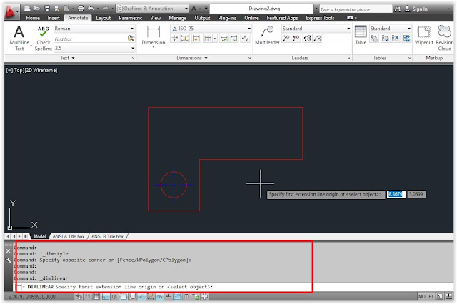
4. Select Dimlinear tool after click on drop down arrow near dimension.
See the below image for what happens after clicking on linear option.
5. Now press key to select object.

6. Now select the bottom line.

7. Now move the cursor slightly downwards and pick the dimension location.

8. Now press ENTER Key to repeat the previouse worked dimlinear commad to activate.

9. Again it prompts “select elements or press enter key to select object”. Now press enter key.
10. Now click on the right most vertical line and move the cursor slightly forward and pick a point.

11. Now click on down arrow from dimension panel and select diameter.
12. Now select circle element and pick a point out side to the object.
13. Now select baseline tool from dimensions.
14.After clicking the baseline option now the dimension dragging with cursor from previous end point of linear dimension.
Now select DOWN ARROW KEY from key board it shows select option and now select this option.
15.Now select the left most dimension line and select next point as shown like below.
16. We must turn ON the object snap icon from status bar to display the end point idnetification.
17.Now select another two points to make dimension.
18.Now pick the dimension lines and move the lines by using blue grip boxes with help of mouse left button.
19. Move the dimensions using left mouse button.
20. Press Esc key to exit from dimension command.
21. Now save the drawing by pressing save icon from quick access tools.
b)Select new document icon from quick access toolbar and open “ansi-a” template.
c)Now click on model layout tab.
d)Click on “LINE” command from draw panel.
e)Now move the cursor to 4 units in X axis and 2 units in Y axis and pick the line stating point.
f)Now move the cursor 2 units horzontally rights side and pick another point of the line.
g)Like wise above steps move the cursor or cross hair to required points shown bellow image and pick the points to get the required shape.
h)Finally enter “C” to close the line.
i)And draw circle by using Circle command.
j)And draw the center lines.
k)Then apply it’s layers accordingly.
Now select HOME tab menu.
2. Now click on layer drop down list by clicking on drop down arrow.
3. Now click on Annotate menu tab to display annotate tools.
4. Select Dimlinear tool after click on drop down arrow near dimension.
See the below image for what happens after clicking on linear option.
5. Now press

6. Now select the bottom line.

7. Now move the cursor slightly downwards and pick the dimension location.

8. Now press ENTER Key to repeat the previouse worked dimlinear commad to activate.

9. Again it prompts “select elements or press enter key to select object”. Now press enter key.
10. Now click on the right most vertical line and move the cursor slightly forward and pick a point.

11. Now click on down arrow from dimension panel and select diameter.
12. Now select circle element and pick a point out side to the object.
13. Now select baseline tool from dimensions.
14.After clicking the baseline option now the dimension dragging with cursor from previous end point of linear dimension.
Now select DOWN ARROW KEY from key board it shows select option and now select this option.
15.Now select the left most dimension line and select next point as shown like below.
16. We must turn ON the object snap icon from status bar to display the end point idnetification.
17.Now select another two points to make dimension.
18.Now pick the dimension lines and move the lines by using blue grip boxes with help of mouse left button.
19. Move the dimensions using left mouse button.
20. Press Esc key to exit from dimension command.
21. Now save the drawing by pressing save icon from quick access tools.


