1. a)Open AutoCAD application from desktop shortcut menu.
b)Select new document icon from quick access toolbar and open “ansi-a” template.
c)Now click on model layout tab.
d)Click on “LINE” command from draw panel.
e)Now move the cursor to 4 units in X axis and 2 units in Y axis and pick the line stating point.
f)Now move the cursor 2 units horzontally rights side and pick another point of the line.
g)Like wise above steps move the cursor or cross hair to required points shown bellow image and pick the points to get the required shape.
h)Finally enter “C” to close the line.
i)And draw circle by using Circle command.
j)And draw the center lines.
k)Then apply it’s layers accordingly.
Now select layers drop down arrow to see the total layer types.
Now click on Lock icon of object layer and we can observe lock to be closed. See the image bellow.
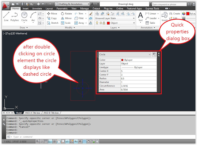
2.Now double click circle element then AutoCAD shows the quick properties dailog box.
3.Now click on radius box in quick properties dailog box and enter the value “1” and press Enter key.
After pressing ENTER KEY the value won’t changed. See the below image.
4.Now again click on layer drop down arrow and click on closed lock icon to open the lock by using left mouse button.
5.Now save the drawing by pressing save icon from quick access tools.


