
How to draw construction lines with angle in AutoCAD

1.
a) Open AutoCAD application from desktop shortcut icon or start menu.
b) Open previously saved document.

2.Click on the drop down arrow near Draw and select “XLINE” tool.

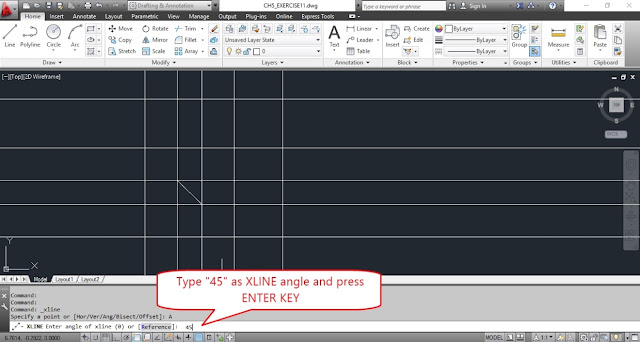
3.Select “Ang” option from command window.

4.AutoCAD prompts for angle to specify.

5.Type “45” as offset angle and press ENTER KEY.

6.Acquired midpoint of inclined line and pick a point of construction line.

7.Press ENTER KEY to exit form XLINE command.

8.Now select XLINE tool from Draw panel.

9.Click on “Offset” tool icon from modify panel.

10.Now AutoCAD prompts for offset distance.

11.Type “.5” as offset distance and press ENTER KEY.

12.Now select the angled construction line.

13.And move the cursor bottom right side and pick a point.

14.Again select angled construction line.

15.Move the cursor top left side and pick a point.

16.Now press ENTER KEY to exit from XLINE command.

17.Save the drawing by click on quick save icon from quick access menu tool bar.


Trending

Draw a line using polar co-ordinate system in AutoCAD

1. Open AutoCAD software from desktop short cut or from start menu.   2. Now type "LINE" and press ENTER KEY. Then enter 0,0 as first point of the line.   3. Then type 5<30 as second point of the line. This "<" symbol is used for the line point moves to 30 degrees from positive x-axis. 4.  Now again type 2.45<270 as next point of the line. 5. After generating the line press <Esc> key from key board to exit from line command. The lines shown like below image. BACK to Day-1 Lessions CLICK HERE to get CAD HOME Work help or project help (paid)

How to draw a line using cartesian coordinate system on graph paper?

The Cartesian coordinate system in two dimensions (also called a rectangular coordinate system) is defined by an ordered pair of perpendicular lines (axes), a single unit of length for both axes and an orientation for each axis. The lines are commonly referred to as the x- and y-axes where the x-axis is horizontal and the y-axis is vertical. The point where the axes meet is taken as the origin for both, thus turning each axis into a number line. For a given point P, a line is drawn through P perpendicular to the x-axis to meet it at X and a second line is drawn through P perpendicular to the y-axis to meet it at Y. The coordinates of P are then X and Y interpreted as numbers x and y on the corresponding number lines. The coordinates are written as an ordered pair (x,y). BACK to Day-1 Lessions CLICK HERE to get CAD HOME Work help or project help (paid)

How to use Cartesian Coordinates in AutoCAD

Cartesian co-ordinate system is used to represent the X and Y coordinate values. We can draw elements by using a Cartesian coordinate system in AutoCAD. Generally in Cartesian coordinate system the x and y coordinate values are separated with comma (“,”). 1. See the two-dimensional cartesian coordinate grid system in the below image. 2. Generally co-ordinate system represents with its x and y co-ordinate values enclose with brackets. The first value in the enclosed brackets is for X value and the second value in the enclosed brackets if for Y value. The below image represents the line from (2,1) to (4,5). Syn: Type "LINE" and press ENTER KEY from key board. (the data we typed is inserted in command window). Then type 2,1 and press ENTER KEY. Then again type 4,5 and press ENTER KEY. Press <Esc> (escape) key to exit from line command. 3. The bellow line is drawn from (-2,-1) to (0,0). Syn: Type "LINE" and press ENTER KEY from key board. (th...

step by step procedure to placing dimensions in AutoCAD 2015

1. a)Open AutoCAD application from desktop shortcut menu. b)Select new document icon from quick access toolbar and open “ansi-a” template. c)Now click on model layout tab. d)Click on “LINE” command from draw panel. e)Now move the cursor to 4 units in X axis and 2 units in Y axis and pick the line stating point. f)Now move the cursor 2 units horzontally rights side and pick another point of the line. g)Like wise above steps move the cursor or cross hair to required points shown bellow image and pick the points to get the required shape. h)Finally enter “C” to close the line. i)And draw circle by using Circle command. j)And draw the center lines. k)Then apply it’s layers accordingly. Now select HOME tab menu. 2. Now click on layer drop down list by clicking on drop down arrow. 3. Now click on Annotate menu tab to display annotate tools. 4. Select Dimlinear tool after click on drop down arrow near dimension. See the below image for what happens after clicking on linear o...

Procedure to publish the drawing set in AutoCAD

1. a)Open AutoCAD application from desktop shortcut icon or start menu. b)Click on “Open icon” and select “welding_fx” file from database files then click on “Open” button to open the document. 2.Type “PUBLISH” command and press ENTER KEY. 3.Select “Welding_fix-Model” from sheet name list and click on “Remove” button. 4.Select “DWF” option from Publish to list. 5.Click on “Publish options” button. 6.Make sure “Multi-sheet file” as Type and “Include” as Layer information for general dwf options. 7.Click on Preview button to preview the drawing and click on close preview button. 8.Click on “Publish” button and give name as “CH15_EXERCISE5” and press ok button. 9.Click on “NO” button.

Change the layers to drawing elements in AutoCAD

1. a)Open AutoCAD application from desktop shortcut menu. b)Select new document icon from quick access toolbar and open “ansi-a” template. c)Now click on model layout tab. d)Click on “LINE” command from draw panel. e)Now move the cursor to 4 units in X axis and 2 units in Y axis and pick the line stating point. f)Now move the cursor 2 units horzontally rights side and pick another point of the line. g)Like wise above steps move the cursor or cross hair to required points shown bellow image and pick the points to get the required shape. h)Finally enter “C” to close the line. i)And draw circle by using Circle command. Now pick a point, that bellow left to the created object by usinng left mouse button and move the cursor upwards left. 2.After picking a point top right to the created object then we can see the all entities in the enclosed window appeared with blue boxes. 3.Now hold down the key from key board and select the blue colored center lines by using left mouse but...

How to create new layers in AutoCAD

1. a) Open AutoCAD application from desktop shortcut menu. b) Click on Layer properties icon from home menu ribbon. 2. After clicking new layer icon, a new layer created with default name “Layer 1” now we can edit this name as “Dim” and press Enter Key from key board. Then the layer created with named as Dim. 3. Again press ENTER KEY to repeat the last command i.e. create a new layer. Then change layer name as “Object”. 4. 5. 6. 7. 8. 9. 10. 11. 12.Save the drawing by clicking on save icon from quick access tool bar. BACK to Day-2 Lessions

step by step procedure to locking and unlocking layers in AutoCAD

1. a)Open AutoCAD application from desktop shortcut menu. b)Select new document icon from quick access toolbar and open “ansi-a” template. c)Now click on model layout tab. d)Click on “LINE” command from draw panel. e)Now move the cursor to 4 units in X axis and 2 units in Y axis and pick the line stating point. f)Now move the cursor 2 units horzontally rights side and pick another point of the line. g)Like wise above steps move the cursor or cross hair to required points shown bellow image and pick the points to get the required shape. h)Finally enter “C” to close the line. i)And draw circle by using Circle command. j)And draw the center lines. k)Then apply it’s layers accordingly. Now select layers drop down arrow to see the total layer types. Now click on Lock icon of object layer and we can observe lock to be closed. See the image bellow. 2.Now double click circle element then AutoCAD shows the quick properties dailog box. 3.Now click on radius box in quick properti...

Step by step procedure to divide elements with help of points in AutoCAD

1. a)Open AutoCAD application from desktop shortcut menu. b)Click on Open icon from quick access tool bar, and select “CH4_EXERCISE” then click on OPEN button to open the previous saved document. 2.Type “DIVIDE” command and press ENTER KEY. 3.Now select the line to be divide. 4.Now enter the value that how many divisions need to divide. Here enter “5”. 5.Now save the drawing by clicking on save icon from quick access tool bar.